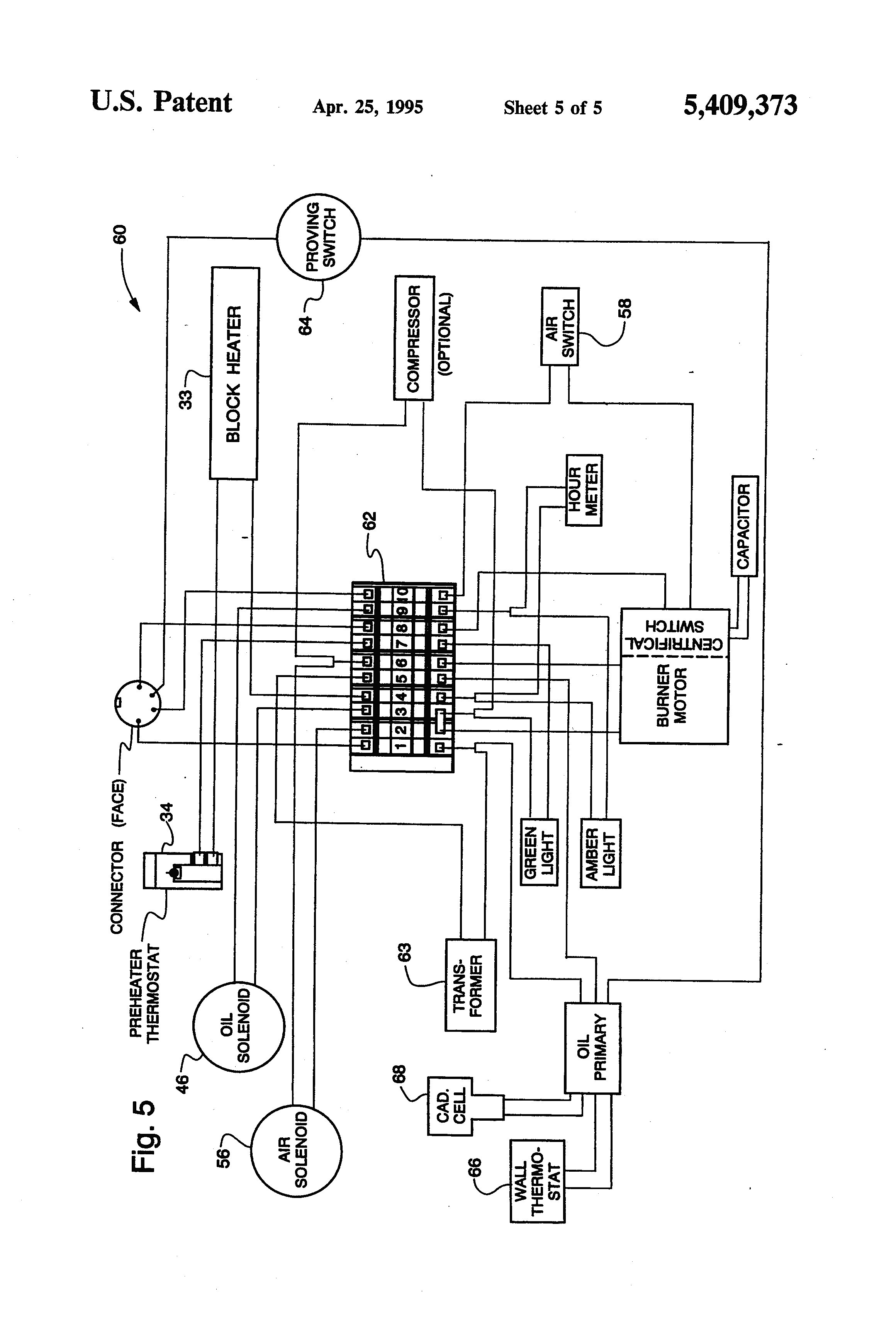
Riello Oil Burner Wiring Diagram

Tempstar Furnace Control Board Wiring Diagram, Tempstar ICP Gas Furnace Circuit Board Replaced, 38.06 MB, 27:43, 22,381, Anti DIY HVAC, 2020-09-10T01:38:43.000000Z, 19, Tempstar Tca030aka1 Wiring Diagram, wiringall.com, 800 x 600, jpeg, tempstar, 20, tempstar-furnace-control-board-wiring-diagram, Anime Arts
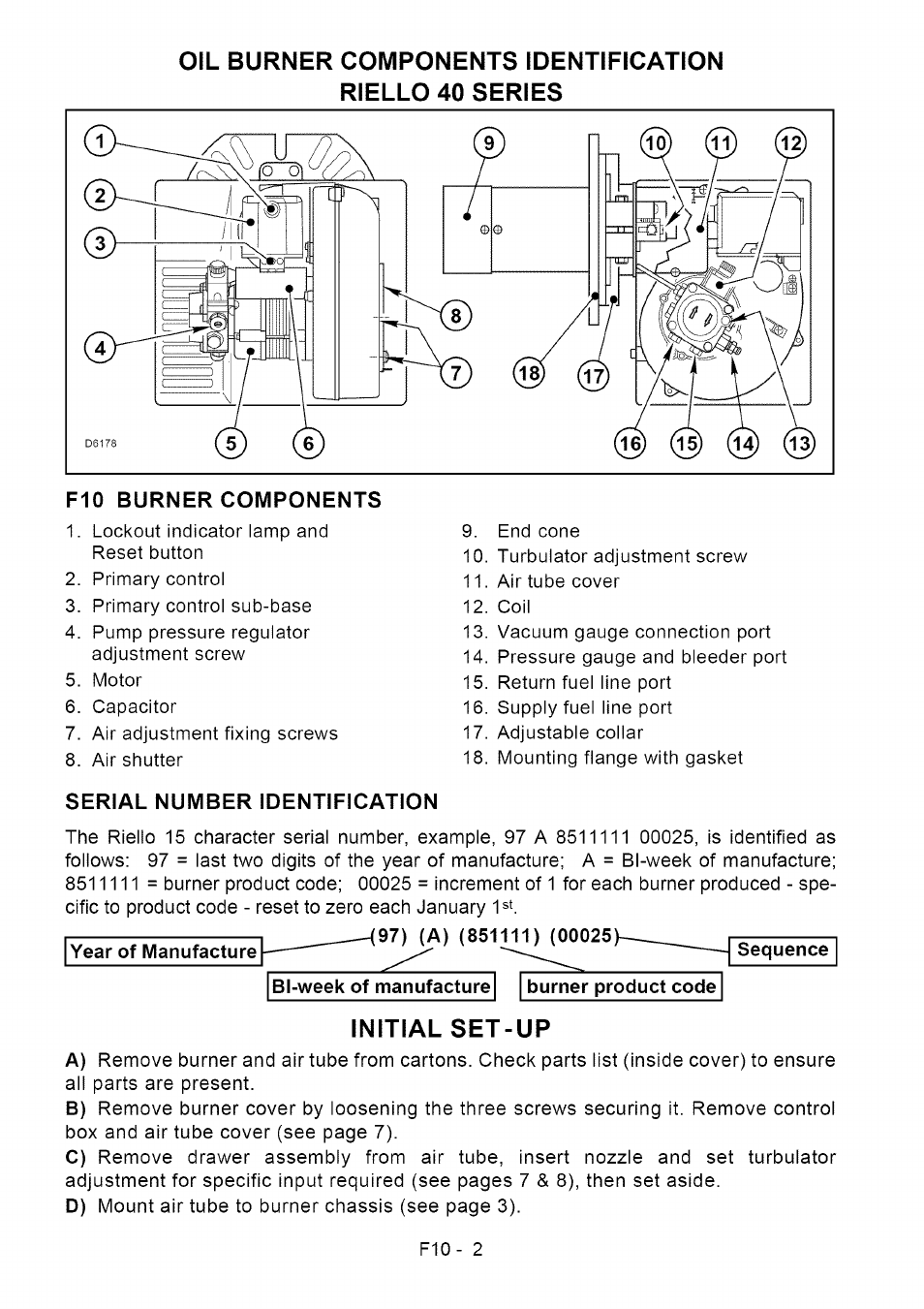
The burner must only be used as expressly described. It can be applied to boilers operating with water, steam, diathermic oil, and to other uses expressly named by the manufacturer; The type and pressure of the fuel, the voltage and frequency of the Riello 40 series residential oil burners note:
If this burner is being installed on a packaged unit (burner comes with the boiler or furnace), then follow the settings on the oem page, as settings may differ. burner is set for a single line system. Application field wiring wiring diagram shown below for standard riello 530 se/c primary control box installation note: Electronic air shutter requires a constant 120v power supply to the aux terminal, failure to provide this will result in no burner operation or air shutter will not close. 3 t (4) operating limit device Oil burner r35 series installation manual if this burner is being installed in a packaged unit (ie. Of the adjacent diagrams. High fire delivery must be selected within area b (and c for model rl 130). Oil line connections this burner is shipped with the oil pump set to operate on a single line system. A pressure gauge is attached to the pressure port (8) for pressure readings.
Riello burner wiring — Heating Help: The Wall

Riello Oil Burner Wiring Diagram - Wiring Diagram

LE L7248 Manuals - Page 11

Riello Oil Burner Wiring Diagram - Wiring Diagram

Riello Oil Burner Wiring Diagram - Wiring Diagram

RIELLO Burner, Furnace Manual L0805012

Riello G20 Light Oil Burner G20 Oil Diesel Burner 40 G20 Buner use for Oven, Baking, Boiler
Riello Oil Burner Wiring Diagram - Wiring Diagram

Beckett Oil Furnace Wiring Diagram

Riello Oil Burner Wiring Diagram - Wiring Diagram

